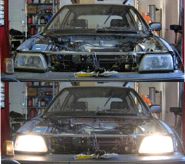
March 2. The car will have a 120 volt DC circuit to run the electric motor, but the car still needs a 12 volt circuit to run the lights, windshield wipers, radio, etc. I have decided on the Iota DLS-45 DC-DC converter, a switched-mode power supply that can be plugged into AC or DC to provide 13.8 volts or 14.3 volts DC. It arrived today from Northern Arizona Wind and Sun.
To check the existing 12-volt circuit, I attached the original battery to the original battery connectors:

Lights, windshield wipers, etc. still work.

Using a volt meter and electric circuit diagrams in my Haynes and Chilton's manuals, I found two wires that show battery voltage when the key is turned on. See red arrows below. The one one the left is about 12 gauge. I'll use that for the vacuum pump. The one on the right is about 14 gauge. I'll use that for the control circuits.

This animated gif shows a voltmeter test with key on and key off:

The key-on position will actuate one of the contactors. It must also tell the controller it's on, and it must start the vacuum pump. I'll have to draw a circuit diagram for my particular set-up.
The DC-DC converter will fit over the passenger wheel well. I made a bracket that bolts where the ignition coil used to be:

I made a simple bent iron strap to secure the other side of the converter:

March 7 - 8. The +12 volt output at the rear of the converter easily connects to one of the fusible links. The other wire bolts to the frame of the car using a 10 gauge crimped ring connector (shown later in the picture of the inertia switch):

With two nice weekend days, I removed the controller board, reservoir, rear battery frame and converter. I sanded a few rusty spots, I washed the engine compartment, primed the rusty spots and painted the engine compartment:

I also primed and painted the brackets for the converter and reinstalled it. I add a terminal strip for the key-on wire since it must go to several places:

March 14. I connected many of the low voltage (12 volts) wires to the components on the controller board. Here is a view from the top:

Here is diagram showing the low voltage wires:

The white and green wires on the left are connected to a key-on wire via the terminal strip as shown in the photo below. The white wires carry 12 volts to the contactor on the left and then to the contactor on the right via the pot box microswitch. When I turn on the key, the left contactor closes. When I push the accelerator, the right contactor closes. Nice! The green wire on the left carries 12 volts to the key switch relay, labeled "relay" in the diagram. It will connect the + end of the big battery pack (120 volts) to the key switch terminal on the controller. The black and white wires from the pot box are the potentiometer wires. They go to the two lower 1/4" terminals of the controller. The black wires go to chassis ground. See below.
I installed the inertia switch behind the passenger headlight. In the event of an accident, this switch will trip and cut the voltage to the controller, shutting it off. The inertia switch can be reset by pressing the orange button on top. The 120 VAC relay is temporarily mounted on the DC DC converter. It will shut off the key-on voltage when activated by the charger line voltage so the car will not run if it is plugged into the charger. This relay will also start the battery box exhaust fan when the charger is plugged in, to prevent hydrogen gas from collecting in the box. Chassis ground is at the bottom of the picture.

March 22. I bundled the white, green and black wires from the controller board into a cable protector. While working with the charger bracket and high voltage cable, I broke the inertia switch mount, so I made a clamp out of a piece of sheet metal:

Lots of new wiring here. I wired a gray Anderson connector that will connect the charger to the battery pack. I installed a white line cord to connect the DC-DC converter to the battery pack when the key is turned on. I am working on the instrument wires, too. I'm nearly ready to order batteries:

April 2. I couldn't test the DC DC converter until today, when I had all the batteries in place and connected. I wired up the converter to the two contactors. One wire goes to the plus side of the battery pack, the other goes to the minus side of the controller, so that the converter gets full pack voltage only when the key is turned on:

I turned the key while checking the auxilliary battery voltage. It went from 12.5 to 13.5 volts, as it should.
May 24. I changed the 120 VAC relay for a simple wall-wart power supply to provide 12 volts for the battery box exhaust fan.. It gets power from the AC line and so will not drain the motorcycle battery.
